Example Architecture - Colocation Management
This is the setup we provide per default for shared colocation customers to access their IPMI and host management via a secure VPN connection.
Features Used
- SDN Networks
- Internet Access
- VPN Access
- Attachments to physical Ports
Architecture
We do not have an existing SDN Network or VLAN, so we start fresh.
We have a single Subnet in our Segment with CIDRs 10.100.10.0/24 and fc00:100:10::/64 which is used for the management of the colocation servers.
The IPMI will get 10.100.10.11, the Proxmox host will get 10.100.10.10.
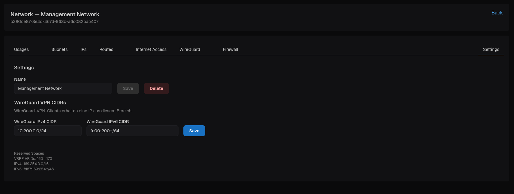
For the VPN Clients, we use the Subnets 10.200.0.0/24 and fc00:200::/64.
On the Colocation Server, we want to have this new Management Segment attached
- untagged on the IPMI Port for IPMI Access and
- as tagged VLAN 10 on the 2x100G data uplinks for Proxmox Access. The data uplinks are bundled with LACP and connected to two separate switches via EVPN-MH.
flowchart LR
    vpnClient[Remote VPN Client<br/>10.200.0.2<br/>fc00:200::2]
    internet@{ shape: cloud, label: "Internet" }
    internet2@{ shape: cloud, label: "Internet" }

    subgraph rltx["realtoxmedia SDN"]
        wg[WireGuard Router]
        nat[NAT Router]
        l3vpn[L3VPN Gateway<br/>Subnet: 10.100.10.0/24<br/>Subnet: fc00:100:10::/64]

        mgmtSwitch["MGMT Switch"]

        subgraph dataStack["Data Switch-Stack"]
            sw1[Switch 1]
            sw2[Switch 2]
        end
    end

    subgraph server["Colocation Server"]
        ipmi[RJ45 IPMI Port<br/><br/>Untagged: MGMT<br/><br/>IPMI: 10.100.10.11]
        bond[LACP Uplink<br/><br/>Untagged: Public IPs<br/>Vlan10: MGMT<br/><br/>Proxmox: 10.100.10.10]
    end

    vpnClient <--> internet <--> wg
    internet2 <--> nat
    nat <--> l3vpn
    wg <--> l3vpn
    l3vpn <--> mgmtSwitch
    mgmtSwitch <--> ipmi
    l3vpn <--> dataStack
    sw1 <--> bond
sw2 <--> bondImplementation
1) Creation of SDN Network
We first create the SDN Network at SDN > Networks using the "Create Network" button. 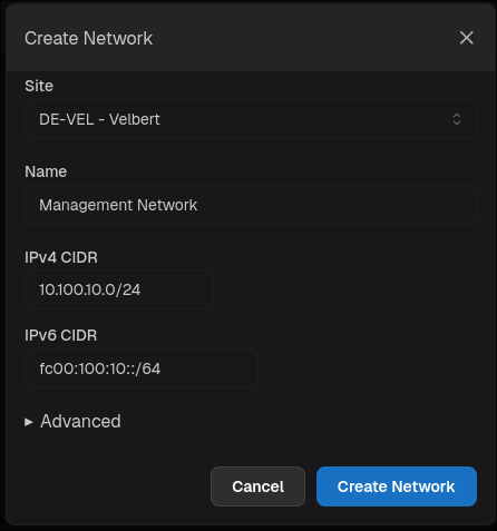
The creation takes about 10-20 seconds to finish.
2) Enable Internet Access
If not already allowed, you need to request the "L3VPN Internet Access allowed" Permission at Settings > Limits.
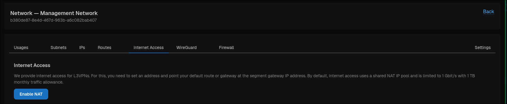
After having been granted this, you can enable Internet Access in the Network's Details Page > Internet Access using the "Enable NAT" button.
3) Configure and Enable VPN Access
If not already allowed, you need to request the "L3VPN VPN WireGuard allowed" Permission at Settings > Limits.
(Optional) Setting the VPN Client Subnet
As we want a custom Subnet for our VPN Clients, we navigate to the Network's Details Page > Settings and set our desired subnets and Save.
Enable WireGuard VPN Access
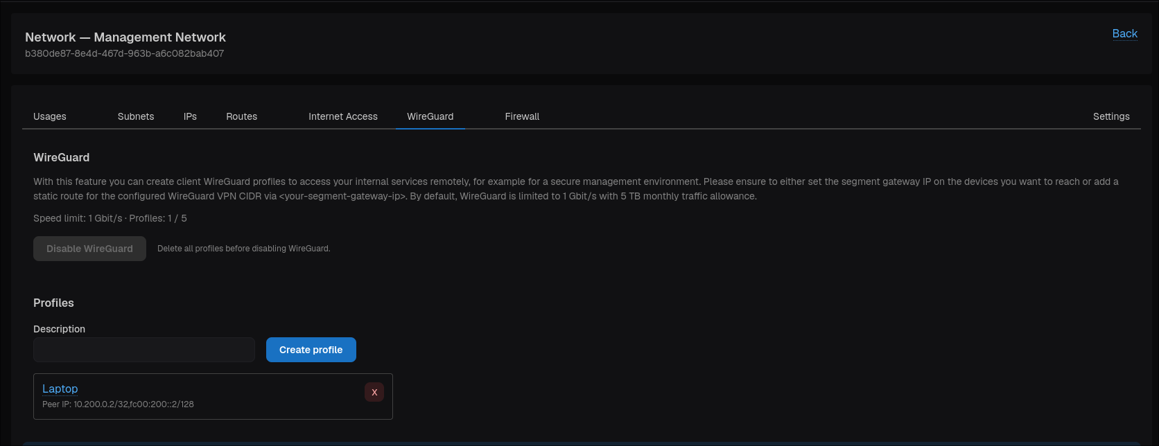
We then navigate to the Network's Details Page > WireGuard tab and enable the VPN Access using the "Enable WireGuard" button.
Creating a WireGuard Client Profile
Now we have a ready wireguard server running and need a wireguard client config to connect from our client to the IPMI.
You can do this in the WireGuard tab too. Enter a Description and hit "Create profile".
You can then view the profile as text or a QR-Code by clicking on the Name of the profile in the below list.
4) Configuring the Switch-Ports
Now Navigate to the Colocation Device's Details Page (Colocation > Devices > Device) to the Network Ports.
IPMI Port
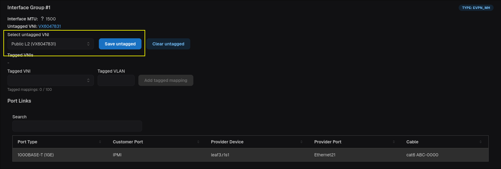
We see that the IPMI Port is "Interface Group #1" and currently has the Untagged VNI "Public L2" set. We replace this with our new Management Segment and Save.
Uplink Bond
We want to add it as a tagged VLAN 10 here. So we select the same VNI, "Management Network", and set the "Tagged VLAN" to 10 and add the mapping. 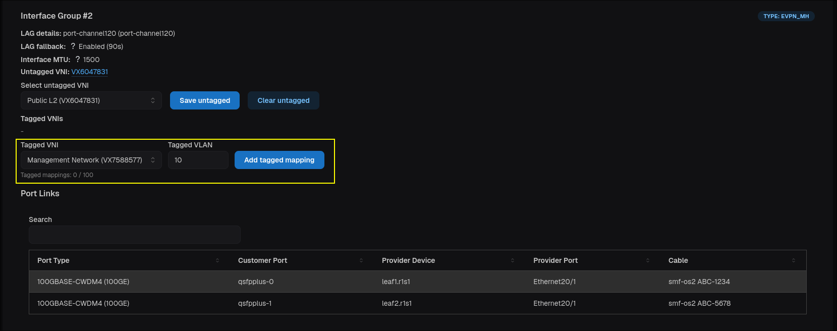
(Optional) Adding Documentation
We recommend documenting the IP-Adresses always, for example in the IPs Tab of the L3VPN Details Page. This way you can always see which IPs are used for which purpose and by which device.
Furthermore, when you document the IPs in the CCP, we automatically provide a DHCP Server for the specified MAC/IP.
For physical Ports this does not happen automatically1. 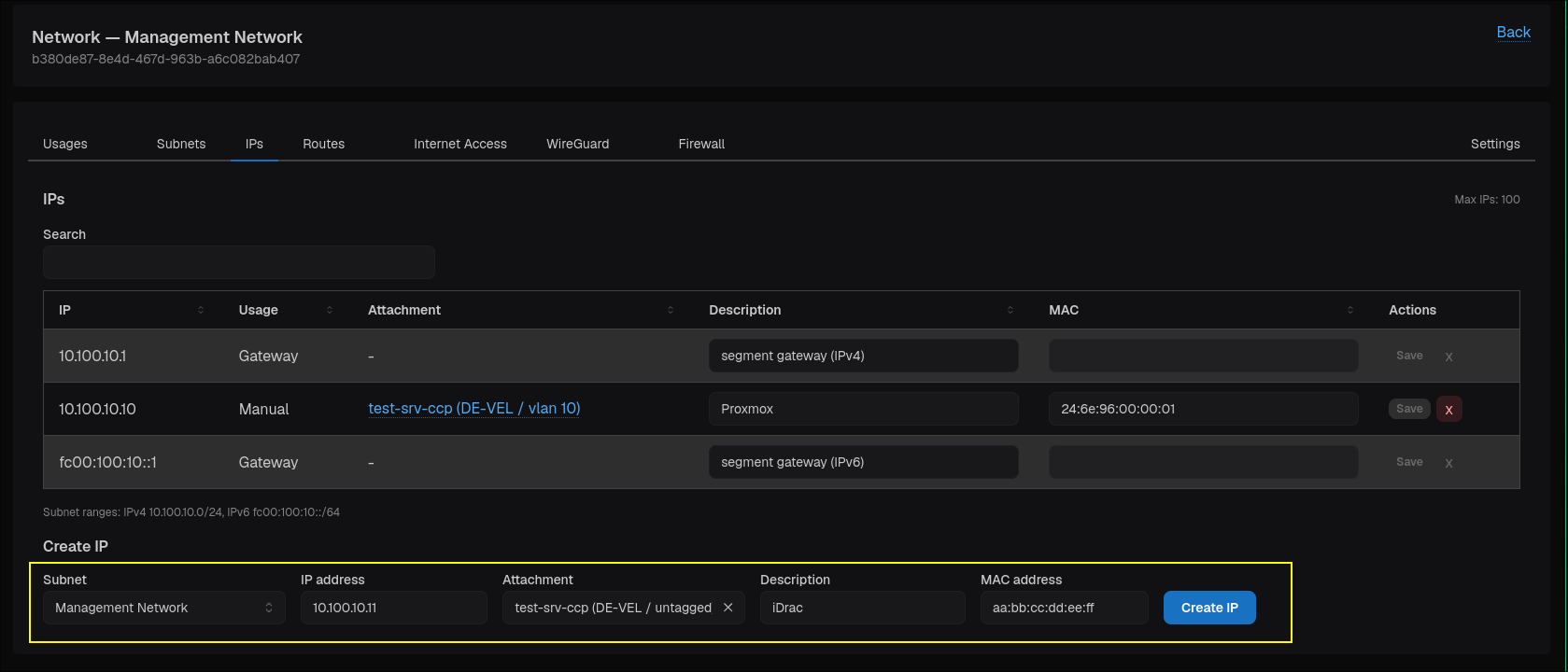
This has architectural reasons. We actually attach the L2VPN to the physical port and do not terminate an L3 (Sub)interface as with VServers or Kubernetes. ↩